The page-level processing means that the basic unit of processing is typically the page, which can be accessed through the handle HPAGE. HPAGE stores a lot of page-related data and information: e.g. the images of the page in different processing phases, zones (areas of the page where the recognition runs), the recognition results (letters, lines, frames). Thus most of the functions require a page as an input parameter.
The Engine can manage more than one page at the same time, as performed by Image Handling Module. Any limit to the number of pages in the subsystem depends on the size of available physical memory and the size of the swap file used as the virtual memory. The Engine can manage and process images of the page within its own memory space only, that is, images need to be loaded into the Engine with the help of the Image File Handling Module.
Within the Engine images can be black-and-white (B/W), grayscale or color.
The unique HPAGE handle is generated by the Engine when the image of the page is loaded. Before quitting, the application should free all pages created in the Image Handling Module (kRecFreeImg).
Image loading
There are three ways to load the image of a page into a HPAGE:
- from a file,
- from the memory of the integrating application,
- from a scanner.
Loading from a file
The Image File Handling Module is responsible for this method.
The function kRecLoadImgF loads an image directly from a file.
The Image File Handling Module provides another way to load image files. This is useful mainly for loading multipage image files, because in such a case, the kRecLoadImgF opens the file page by page. But the given file can be opened calling kRecOpenImgFile. In this case, the page can be loaded from the opened file calling kRecLoadImg page by page. After loading the required pages of the file, it can be closed by kRecCloseImgFile.
A wide range of image file types can be used in CSDK both for loading and saving. For more information, see Image file format list. At loading, some conversion may be performed on the image, which is called primary image conversion.
- Note:
- The following sample shows a simple multi-page image file processing:
    RECERR rc;
    // Open a multi-page image file.
    HIMGFILE hIFile;
    rc = kRecOpenImgFile("testfile.tif", &hIFile, IMGF_READ, (IMF_FORMAT)0);

    // Get the number of pages
    int pageCount;
    rc = kRecGetImgFilePageCount(hIFile, &pageCount);

    // Process the pages.
    HPAGE hPage;
    for (int i=0; i<pageCount; i++)
    {
        rc = kRecLoadImg(0, hIFile, &hPage, IMGF_NEXTPAGE);
        ...
        // Process the current page (preprocess, recognize,
        // output conversion, etc.)
    }
    // Close image file.
    rc = kRecCloseImgFile(hIFile);
Loading from the memory of the integrating application
The Image File Handling Module and Image Handling Module are responsible for this method.
The function kRecLoadImgM can be used for loading an image from the memory of the integrating application.
When loading a Windows DIB (device-independent bitmap), the integrating application should set the lineorder, the padding and the order of the color components of the image settings as follows:
rc = kRecSetImgFormat(0, BOTTOM_UP, PAD_DWORDBOUNDARY, COLOR_BGR);
There are two other ways for transferring an image from the application's memory to the Engine's memory space: either a line-by-line method or when the whole image is transferred at once (or at least in big chunks).
The latter method requires that you create an empty image first, using the kRecCreateImg function and then to transfer chunks of the application's bitmap into the image by invoking the kRecPutImgArea function that can place the bitmap area into the image frame, stretching or compressing it, as necessary.
To transfer an application’s bitmap to the Engine line-by-line (e.g. during a fax transmission), the following steps should be taken. First, the kRecStartWriteImg function has to be invoked with the address of a filled IMG_INFO structure that describes the size, the resolution, and the bits per pixel value of the image. It is not necessary to specify the BytesPerLine field and if the number of lines is not known, the Size.cy field can be zero. The kRecSetImgFormat can be used for specifying the line order, the RGB order and the padding, before initiating the line-by-line image transfer.
Subsequent calls to the kRecWriteImg does the real work by adding lines to the image. The integrating application should call the kRecStopWriteImg function when all the lines have been transferred and you want to indicate this fact to the engine. As a result, you will get a new HPAGE.
If the image being loaded is a B/W one, the representation of black pixels in the application memory bitmap should be ONE (1), while the whites should be zero (0). If the image in memory is the opposite (1=white, 0=black) the application can invert the data first or use SDK preprocessing functions to invert the image after it has been loaded into Engine memory. (See Preprocessing)
Loading from a scanner.
The Scanning Module is responsible for this method. The Scanning Module is supported on: Windows
When scanning is required, the Engine's scanning subsystem must be initialized separately. The reason for this additional initialization is that the scanning subsystem can work on its own without the recognition or other non-essential modules. It supports a wide selection of scanner models through TWAIN or WIA. For a list of the extensively tested supported scanners, please visit http://support.nuance.com/compatibility page. Of course, if your hardware is not listed you may still be able to use it with your CSDK, because it is not a full list.
There is no point in initializing the scanning subsystem if there is no working scanner connected to the computer.
Preparing the scanning subsystem for scanning requires the following steps:
- The scanning subsystem must be initialized for current scanning by the kRecScanInit function. Any other scanning function can only be called after the successful initialization of the scanning subsystem.
- The scanner type must be set through the kRecScannerWizard function that will launch the Scanner Setup Wizard.
To initiate a scanning session, call the initializing kRecScanInit function, to terminate the running of the scanning subsystem call the kRecScanQuit function.
After having initialized the scanning subsystem and adjusting particular scanning parameters (if required), the application uses the function kRecLoadImg with the special input parameter IMGF_SCANNER. Of course, this special type of usage requires neither opening (kRecOpenImgFile) nor closing (kRecCloseImgFile). The Engine loads the image from the scanner into a HPAGE.
Once the application is aware of the scanning capabilities of the installed scanner driver/type, the application can adjust or learn the current scanning parameter settings by accessing the kRecSetScanXX and kRecGetScanXX functions, respectively. For example, one of the most important settings specifies what kind of image the scanner provides, i.e. whether the image output from the scanner should be B/W, grayscale or color. This setting can be specified through the kRecSetScanBitsPerSample function and it can be retrieved by kRecGetScanBitsPerSample.
Saving images
Saving to a file
If the integrating application requires saving a whole page image (or a portion of it) to a file, this can be done in similar ways to the loading.
It is possible to save the image directly into a file using kRecSaveImgF or kRecSaveImgAreaF.
The other way is to open a new file calling kRecOpenImgFile, to save pages into this file using kRecSaveImg or kRecSaveImgArea, and to close the file (kRecCloseImgFile).
When saving an image, the application programmer must specify the format and compression method for the output image file (see IMF_FORMAT or Image file format list). When a multi-page image file format is the destination using the first way, the method of saving should be specified: overwrite the current contents or append to it. If you are unsure whether the chosen image file format supports multi-page image files you can determine this with the kRecIsMultipageImgFileFormat function.
The Capture SDK supports the following multi-page image file formats for writing: DCX, MAX, TIFF and image-only PDF.
Similarly, to avoid problems, the application can check whether the selected image file format can accommodate the current image with the kRecMatchImgFileFormat function. The application can determine for example, whether the selected output can accommodate grayscale images.
Saving to the memory of the integrating application
The images stored in the Engine cannot be manipulated directly by the integrating application since the Engine incorporates its own Image Handling Module. Internally the images are usually kept in compressed mode in the Engine's memory and only uncompressed when necessary. When the application requires a part of an image or the whole image, e.g. for visualization purposes, it can get it by invoking the kRecGetImgArea function.
If the image is a B/W one, the representation of black pixels in the created bitmap will be ONE (1), while the whites will be zero (0), i.e. for displaying the image use the NOTSRCCOPY raster operation code. The (0,0) point of the image coordinate system is always the upper left corner of the image.
The kRecSetImgFormat function can be used to specify how the application would like to get the new image in its memory space. With this function the application can specify the line order, the padding and – for color images – the RGB order attributes of the new image.
If the image area to be copied also needs to be rotated and/or mirrored, use kRecRotateImgArea as an alternative to kRecGetImgArea.
To perform reading an image line-by-line from the Engine's memory space and transfer it to the application, the functions kRecStartReadImg, kRecReadImg and kRecStopReadImg work similarly to the line-by-line writing described in the topic Loading from the memory of the integrating application.
Preprocessing
As mentioned, the HPAGE contains different phases of the loaded image. There are some functions in the Image Handling Module, which work on a particular phase of each image. For specifying one of these phases, use the identifier IMAGEINDEX. The function kRecGetImgInfo gives information about the given phase image of the page.
If the primary image conversion during loading does not run a secondary image conversion may be required, because the recognition process runs on B/W images. This latter conversion type can be called through kRecConvertImg2BW or implicitly. The implicit secondary image conversion may be required if the integrating application asks for a B/W image or for an operation running on B/W images (e.g. the recognition itself), but it has not been created before in the given HPAGE. The primary image conversion mode can be selected by the User through kRecSetImgConvMode. A secondary conversion is influenced by kRecSetImgBinarizationMode.
Before zoning and recognizing (or even saving) a page, SDK functions can be used to apply some image pre-processing procedures to enhance the quality of an image resulting in more accurate auto-zoning and recognition. This is typically done with the function kRecPreprocessImg, which can include any or all of the following steps:
- Inversion: automatic, programmed or none;
- Rotation: automatic, programmed or none;
- Deskewing: automatic, programmed or none.
The following functions let you define the behavior of these image enhancement steps: kRecSetImgInvert, kRecSetImgRotation, kRecSetImgDeskew and kRecSetImgSlope.
In addition to these operations, sometimes image despeckling and resolution enhancement are also performed internally to improve the success of image pre-processing.
The image pre-processing functions can also be called one by one as the following:
- inverting - kRecInvertImgArea,
- rotating - kRecRotateImg,
- deskewing - kRecDeskewImg,
- despeckling - kRecDespeckleImg,
and there are some functions for doing user-defined transformations: kRecTransformImgXX.
When the application calls any of these functions, the appropriate image enhancement step is immediately performed on the image of the page and the result is available to both the Engine and the application as described in the detailed description of each such function.
For more information, see the description of the above mentioned functions and that of the following types:
- inverting - IMG_INVERT,
- rotating - IMG_ROTATE,
- deskewing - IMG_DESKEW,
- resolution enhancement - IMG_RESENH.
Zoning
The Zone Handling Module is responsible for creating and handling zones.
The zone is a rectangular area or the union of specifically located rectangular areas in the page. The upper limit of its dimensions is full page size. The zone contains a feature of interest to the User. The union of rectangles must have a so-called pizzabox shape: the top of each rectangle in the union must touch the bottom of the above rectangle (i.e. the bottom of the upper rectangle and the top of the lower one is exactly the same). A rectangle can touch at most one rectangle above and one below. A pizzabox-shaped zone is a compound and irregular zone.
The image data covered by each zone is handled and processed (typically recognized) separately, according to zone-specific parameters. These parameters are collected in the structure ZONE.
NOTE: In both the SDK and its documentation, coordinates refer to grid-coordinates - i.e. the top or left borders of pixels. Thus a rectangle does not contain the pixels according to its right and bottom coordinates.
Any HPAGE can contain two types of zones in zone lists:
- user zones and
- OCR zones.
The characterizing attributes of a zone are the following:
- size and position,
- index of the zone (identifies the zone in the appropriate zone list),
- type (determines the role of the zone in the image layout, i.e. Flowed text, Rotated text, Vertical text, Table, Form or Graphic),
- filling method (specifies the nature of the zone content, i.e. how the zone's area was supposed to be filled originally),
- recognition method (the recognition module to be applied for the zone),
- a Character Set filter,
- what kind of spell checking is enabled for the zone content.
If the recognition module and/or filling method are not specified (RM_AUTO, FM_DEFAULT), Engine-level pre-defined settings contain the values determining the processing of such zones (kRecSetDefaultRecognitionModule, kRecSetDefaultFillingMethod).
The user zones are defined by the User. The OCR zones are created by the page parser process, which detects the OCR zones and fills the OCR zone list. When there are user zones, the page parser creates one or more OCR zones from each user zone and it may process the area outside the user zones, as controled by the page descriptor.
The type of OCR zones can be only WT_FLOW, WT_TABLE, WT_FORM or WT_GRAPHIC. The created OCR zones always inherit the attributes (e.g.: filter, filling method, etc.; see ZONETYPE) of the user zone inside which they were created. If the OCR zone is created outside of user zones, its attributes will be set to default for filling method, recognition module, filters and spell checking related properties.
The recognition process (kRecRecognize) works on OCR zones.
The number of zones in the zone lists can be queried at any time using the functions kRecGetZoneCount and kRecGetOCRZoneCount. All functions that use an index to determine the zone to be queried or modified may receive the index -1. This refers to the last zone in the given zone list. Exception: kRecInsertZone : this inserts the new zone behind the currently last zone that receives -1).
Zones can be added to the zone list of any given HPAGE in three different ways:
- add zones automatically (auto-zoning) - use it to add OCR zones
- add zones manually (by specifying the zone coordinates and attributes - use it to add user zones, or
- add zones from a zone file (a storage file) - use it to add user zones.
Auto-zoning
The automatic page-layout decomposition process (auto-zoning) can be activated directly by calling the kRecLocateZones function for finding text blocks on the image. It creates an entire OCR zone list for the given HPAGE.
OmniPage Capture SDK offers three different algorithms to be applied during auto-zoning: use the kRecSetDecompMethod function to specify which of these Page parser algorithms should be applied during auto-zoning. For details, see also IMG_DECOMP.
In some cases, the process will attempt to find horizontal and vertical rule lines.
OCR zones may be changed by the recognition process (kRecRecognize), because some post-processing operations have such effects. For example, when non-gridded table detection (kRecSetNongriddedTableDetect) runs during the recognition process.
Any zone can be locally overridden with the functions kRecUpdateZone and kRecUpdateOCRZone. These allow you to change the attributes of a zone in the zone list. Note that the fields ZONE::rectBBox, and ZONE::type cannot be modified by kRecUpdateOCRZone.
Adding zones manually
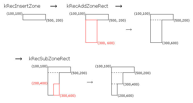
You can choose to search for zones automatically, and/or create your own zones: user zones. To add simple zones to the zone list manually, use the kRecInsertZone function. To add/subtract a rectangle to/from an existing user zone, use the functions kRecAddZoneRect or kRecSubZoneRect.
- Note:
- The following code sample demonstrates the creation of user zones and the results of the above operations (two rectangles are added, but the subtraction produces a result that can only be described by three rectangles fulfilling the requirements of the pizzabox shape):
-
It is recommended to use the function
memsetfor filling aZONEstructure with zero before setting its fields. In such a way, a WT_FLOW zone is created with default fields, thus the application must set only the non-default fields before inserting the zone.
    RECERR rc;
    // Create a zone structure.
    ZONE zone;
    memset(&zone,0,sizeof(ZONE));
    zone.fm=FM_OMNIFONT;
    zone.rm=RM_OMNIFONT_MOR;
    zone.filter=FILTER_ALL;
    zone.rectBBox.left=100;
    zone.rectBBox.right=500;
    zone.rectBBox.top=100;
    zone.rectBBox.bottom=200;

    // Add it to the page.
    rc = kRecInsertZone(hPage, II_CURRENT, &zone, 0);

    // Extends the zone with a new area.
    RECT rect;
    rect.left=100;
    rect.right=300;
    rect.top=200;
    rect.bottom=600;
    rc = kRecAddZoneRect(hPage, II_CURRENT, &rect, 0);

    // Removes an area from the zone.
    rect.left=200;
    rect.right=300;
    rect.top=400;
    rect.bottom=600;
    rc = kRecSubZoneRect(hPage, II_CURRENT, &rect, 0);

    // Get the zone's layout.
    int nRects;
    RECT *rects;
    rc = kRecGetZoneLayout(hPage, II_CURRENT, &rects, &nRects, 0);

    // Print the zone's layout.
    for(int i=0;i<nRects;i++)
    {
        printf("%i. rect: Left:%i Top:%i Right:%i Bottom:%i\n",
            i,rects[i].left,rects[i].top,rects[i].right,rects[i].bottom);
    }

    // Free up the layout information given back by the kRecGetZoneLayout function.
    rc = kRecFree(rects);

    ...

    // The generated output:
    // 0. rect: Left:100 Top:100 Right:500 Bottom:200
    // 1. rect: Left:100 Top:200 Right:300 Bottom:400
    // 2. rect: Left:100 Top:400 Right:200 Bottom:600
The following figure shows the progression of the above sample code.
Adding zones from a zone file
The third way of creating zones is to have zones read from a file (called a zone file) that contains the attributes of previously saved zones. Zones created this way will also be user zones. An integrating application can save the current user zone definitions to a zone file any time with the kRecSaveZones function. The application can load them from a zone file with the kRecLoadZones function.
NOTE: When a zone file is loaded, any previous zones are removed from the page.
Modifying zones
If the application calls the kRecRecognize recognizing function on a page with an empty zone list, the page-layout decomposition function is called automatically.
To get information about any particular zone in the image zone list, invoke the kRecGetZoneInfo and kRecGetOCRZoneInfo functions. These functions are useful to find out more about zones created by auto-zoning.
NOTE: When you update a table-type zone with the kRecUpdateZone function, the cell-detection algorithm will not be activated, resulting in improper table detection within the zone. See the description of creation of table information.
Any changes in the user zone list (kRecInsertZone, kRecDeleteZone, kRecDeleteAllZones, kRecAddZoneRect, kRecSubZoneRect, kRecLoadZones, kRecUpdateZone, kRecSetZoneLayout) will make OCR zones invalid, the OCR zone list will be emptied and regenerated.
- Note:
- The following code selects an exact recognition engine (DOT) for all the OCR zones before recognition:
    // Page parsing.
    RECERR rc = kRecLocateZones(0, hPage);

    // Get the number of zones.
    int nZones;
    rc = kRecGetOCRZoneCount(hPage, &nZones);

    // Cycle through zones.
    for(int i=0; i<nZones; i++)
    {
        // Get zone information.
        ZONE zone;
        rc = kRecGetOCRZoneInfo(hPage, II_CURRENT, &zone, i);

        // Change zone filling method and recognition module.
        if(zone.type != WT_GRAPHIC)
        {
            zone.fm = FM_DRAFTDOT9;
            zone.rm = RM_DOT;
        }

        // Change the zone.
        rc = kRecUpdateOCRZone(hPage, II_CURRENT, &zone, i);
    }

    ...

    rc = kRecRecognize(0, hPage, NULL);
Page descriptor
The page description describes the possible layout elements (text, table, graphics and form) on the page outside of the user zones. These layout elements are found by the page-parse and the recognition processes. The page description has no effect inside the user zones. The LZ_COLUMN / LZ_TABLE / LZ_GRAPHICS flags specify how to find text / table / graphic zones.
For more information see the detailed description in Usage of Page Descriptor.
Table detection
The Table Recognition Module detects tables on the page and assigns the appropriate parts of the recognition results to each table cell, based on the collected table information.
A table is described by the list of its cells in reading order (from left to right and top to bottom) ordered by their top-left coordinates. A cell is always a rectangle, thus a table is a sequence of rectangles.
All cell operations must adhere to the following restrictions:
- cells cannot have blank spaces between them,
- cells cannot intersect each other
- all cells must have a rectangular shape.
Table information in a table zone (WT_TABLE) contains the above mentioned table description. (See CELL_INFO.) The structure of a table zone can be determined in three different ways:
- User-defined: creating a one-cell table structure (kRecCreateTableInfo) into a
WT_TABLEuser zone. Having such table information the User can insert splitters into it (kRecSplitCells), or can replace the cell list to a User-defined cell sequence (kRecSetCells). Note thatkRecSetCellscreates the table information, ifkRecCreateTableInfohas not run beforehand. - User-started: calling kRecLocateTable for a
WT_TABLEuser zone before recognition. The module automatically detects the structure of the table covered by the given zone and creates the table information. - Engine-controlled: the recognition process automatically detects and creates the table information for all such
WT_TABLEuser zones that have not been processed by the previous two methods and for all the automatically detected table type OCR zones.
The User-started method is less accurate than the Engine-controlled one, thus it may be useful only when automatic cell detection is required before recognition (mainly for displaying on the UI).
The Engine-controlled method leaves the existing cell sequence, if any. In contrast, the User-started method recreates the cell sequence of the user zone even if the zone already contains table information.
It follows from the above that the Engine-controlled method can be disabled calling kRecCreateTableInfo.
It is also possible to detect tables having invisible cell-separators (so-called non-gridded tables); see the description in kRecSetNongriddedTableDetect.